Title: FARMERS OBEDIENT MOTOR STARTER
Author: PINNAKA VINAY DATTA, 4th Year BTech, Electronics & Communications Engineering
College: Prakasam Engineering College, Kandukur
ABSTRACT:
Basically India is an agriculture country but now the contribution to world’s agriculture productivity by India has been declined. As innovative engineers of India it is our responsibility to retain the glory of India in agriculture production by implementing the technology in our labs to our farms.
PROBLEM STATEMENT:
Most of the agriculture lands in India are highly productive but the problem lies in irrigation. Irrigation plays a dominant role in agriculture; most of the productive lands use ground water irrigation since there is no proper rainfall in present situations. Ground water irrigation have a basic need that is electricity, As we know that Indian electricity has 0.5 probability it may or may not be present at any instant. With this irregular power cuts it is very difficult to depend on ground water irrigation, but there is no alternative. So to overcome this problem we need to utilize electricity whenever it is present.
To illustrate this consider a small example, a farmer switched farm motor ON conforming that power is present. Suppose if his farm needs to be watered for at least 2:00 hours as usual farmer left the field and went for another work, when he returns he was surprised to see that even a part of his farm was not watered this is because of regular Indian power cuts. We can’t predict when power comes and when it goes off. Now farmer again has to wait until power resumes and again switch on his water motor. Sometimes power comes during odd nights so that farmer has to sleep in the farms during nights which is dangerous and risky. All this are daily problems faced by the Indian farmers. It is sorry to say that many farmers died of electric shocks while switching the motor at nights. The valuable life of farmers can be saved by a simple innovation which is our project
PROPOSED SOLUTION
If we make the motor starter intelligent so that it can automatically switch on and off then the problem is solved but to implement this self controlled motor stator we need a basic microcontroller has to be programmed with a internal timer must be taken from keyboard where farmer enters the preset time for which his farm has to be watered for illustration a simple example:
If a farmer has to water his chilly field for this we need 2:30 hours then with this ‘Fom starter ‘ what to do is just type the digits ‘2’ ‘3’ ‘0’ and press set button, MCU will take this inputs for timer operation and whenever power comes the timer starts counting motor is on by the stator .if in case power cut immediately then the timer pauses at that instant and again when power comes timer resumes from the previous paused instant of time. After completion of the preset time the motor goes off immediately.
If we want to again set the starter what we has to do is just press reset button so that timer reset to zero (0).now you can input the required time and again press set so the cycle repeats.
HOW THIS HELPS THE FARMERS?
As the motor switching operation is automatic farmer need not to wait for the power to come he has to just set the time in MCU and need not to wait in farm sleep in farm during nights so this simple equipment gives him relief from unusual power cuts MCU is battery operated so that it can retain the timer value until the power comes power and entire working details are explained in the hardware description section.
HARDWARE DESCRIPTION:
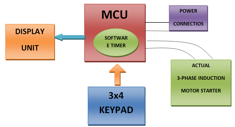
Heart of this Fom starter application is the code written for the MCU. Generally every MCU is designed with internal timers and these timers can provide delay up to a few milli seconds. But to achieve a time delay of hours it is somewhat difficult.
BLOCK DIAGRAM
How the code for MCU is written:
Suppose MCU with 16 bit timer provides 50msec delay then to get a delay of 30 minutes the code written is like this.
Rotate the loop for 30 times /*delay of 30minutes is obtained*/
{
Rotate this loop for 60 times /*delay of 1minute is obtained */
{
Rotate this loop for 20 times /*a delay of 1second is attained i.e.; 50msec x 20 =1second*/
{
Delay of 50msec
}
}
[Small variations in the timer approximately in milliseconds which can be corrected by proper selection of loop rotations]
The data 30min is to be taken from the key pad which is 3×4=12 keys keypad of which 10 keys bear 0 to 9 digits and the remaining are set and reset buttons. The data is stored in MCU by the software program. Detection of key pressed is also done by the software code along with this key pad display unit simple three 7 segment display one for hours and remaining two for minutes the. The display on this 7-segment display is also performed by the code.
HARDWARE INTERCONNECTION:
Keypad is connected to one of the port of the MCU and 7-segment display units use another port .MCU has to take input from the supply whether it is present or not so a port bit is used for this purpose. An MCU has to control the on and off switches of motor starter so, another two bits are used for outputs .this output bits are followed by driver ic’s for better protection of MCU from sourcing large current’s.
POWER CONNECTIONS:
The second major discussion is about power connections. Generally farmers is 3-phase motor for their fields but our MCU is operates on 5v dc. So, a rectifier circuit has to do this supply conversions .one more important caution is MCU timer must start only when all the three phases are present because form motor is 3-phase and it can’t be operated on 1-phase supply.MCU is operated in the battery power which is charged from external supply continuously because all the 3-phases doesn’t goes off at a time any one of the phase will be always present on the line .so the battery is charged by that phase supply present on the line in case if all the 3-phases goes off at a time the fully charged battery acts as source for MCU.
COST ESTIMATE:
1. Since a low power low cost MCU is the only part of the circuit it doesn’t cost’s much
2. On our approximate analysis this entire circuit can be prototyped at the cost of Rs.1000/-
3. Any farmer can afford this because this is the best application of that price
FLEXIBILITY OF CIRCUIT
1. The entire prototype made is highly flexible because it can be operated on single phase as well as three phase by implementing a simple change in code
2. Add-on’s can also be used for this circuit for better performance
3. the major add on which we proposed to built for this circuit is phone call indication
When power is on and off
4. for this add-on we need a old unused phone with its headset
5. we use this phone at the form which is connected to the MCU via a driver
6. whenever power comes a call is made by MCU to the last dialed number
7. so that you can get an indication that power has come or power is gone
8. similarly many other add-ons can be added to this circuit
HOW A FARMER IS SATISFIED BY OUR IDEA
1. He needs not to wait at his farm all the time for the power to come
2. He can be freed from the tension of irregular power cut
3. Electric shock’s can be prevented
4. Waste of time and money can be avoided
CONCLUSION:
As a farmer’s son I knew the basic problems of a farmer and this is one of the solutions to avoid some risks. I feel responsible to retain the glory of India as a agricultural country
Idea for this paper is taken from real world hence references used is most likely only for programming concepts of MCU.
REFERENSES:
http://en.wikipedia.org/wiki/Microcontroller
http://www.newbiehack.com/MicrocontrollerWritingthefirstprogramandtransfer.aspx

